Monitoring fuel levels with lasers and ultrasound
Deciding to buying an older house (90 years in this case) comes with some consequences. Things bend and creak and wobble in ways that they wouldn't in a new build, and you end up inheriting the accumlated decisions that have been made over the years.
In our case, that included the heating system - when it was installed in the mid-90s it must have cost a fortune, and it's still running reliably 20-odd-years later. But it shows the priorities of the times, not least in the choice of fuel, because it burns oil. Bar coal, it’s probably THE most polluting form of heating available.
It will get replaced with something more modern and less CO2-emitting next year, but in the meantime we’ve got the rest of the this winter to get through.
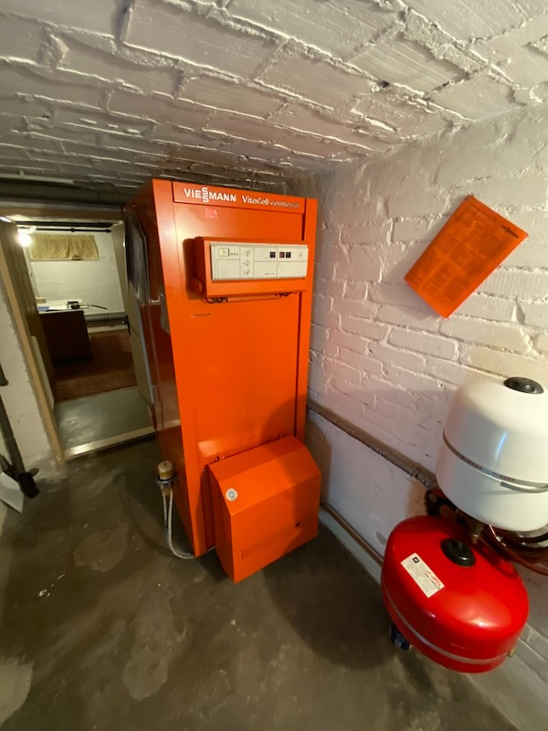
Most of the system is taken up by the hot water storage tank - the oil burner bit is the box at the bottom by the floor. You can just make out the fuel pipe and filter on the left-hand side. The control panel is the beige box on the front
One of the advantages of modern systems is that most of them are connected and make information about consumption and performance available. Right now, though, I’m stuck with a semi-analogue closed system that was designed and built before the web took off, let alone the concept of the internet of things.
There’s some processing power inside, but it runs on a proprietary protocol that’s long-since been abandoned. I did vaguely wonder about poking around and trying to reverse-engineer what’s going on, but it’s a working system that we rely on for heat and hot water, and I’d be domestically unpopular if I broke it.
The ultimate solution is to rip out the old and replace it with the new - but I also like the idea of being able to squeeze some extra life out of legacy equipment by wrapping around it with new digital parts.
Specifically I want to know how much oil is being consumed. The oil is stored in an interconnected network of six 750 litre tanks in the cellar, but there’s no way of getting consumption stats out of either the tanks or the boiler itself. The previous owners were marking the side of the tank with the oil levels at a given date, but that’s no use for my purposes.
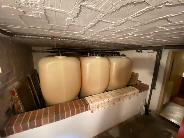
There's another 3 tanks behind these, and they're all interconnected with the black pipework above. It's a bit difficult to see, but they have a "waist" just below the wall, which makes the volume calculations more complex
My first idea was to measure the fuel flow as it’s consumed, but that was a non-starter for several reasons. Digital fuel flow meters that could be retrofitted to the system are prohibitively expensive, and fitting would involve chopping into the copper fuel lines.
That’s not technically difficult, but it does need specific tools for the job (which I’d end up using once) and it’s a high-peril process. Get it wrong, and there’s 4.500 litres of oil all over the floor…
The second approach was measuring the level of fuel in the tanks. I know their dimensions, and therefore volume; and all six are interconnected so that the level drops at more or less the same rate in all of them. If I could somehow measure the depth of the remaining fuel, from there I could get the consumption rate.
There’s a range of approaches used by commercial products - the most basic and analogue is some kind of dipstick, but I rejected that on the basis that it’s a) analog, b) requires me to do it regularly and c) involves splashing around in diesel.
Some more exotic options are barometric devices which have a pressure sensor at the bottom of the tank and measure the height of the fuel through pressure changes, but these are also spendy and closed.
Going back to a “digital dipstick” concept, I came across an ultrasonic sensor that screws onto a filler vent and measures the distance between the sensor and the top of the fuel. These aren’t too expensive, but fail on the connected criteria - they’re basically fancy tape measures which would give me a number, but not integrate in any useful way.
It shouldn’t be too difficult to home-brew, right?
Spoiler - it’s not. I stole the idea of something that would screw onto the vent, and I've replicated with the connectivity that the commercial products don't offer.
Attempt #1 was using a laser “time of flight” sensor because, well, lasers. Effectively they're a combination of an pulse-firing infrared laser and a very accurate clock that measures the time between the flash being emitted and the reflection hitting a sensor on the return. They’re very, very small and work over the kind of distances I’m having to deal with (the tanks are just under 2m tall).
Outside of the tank, the sensor worked reasonably well, but once mounted inside it was hopeless. I think this is due to the reflectivity of the surface of the oil not being optimised for the wavelength of the IR light - but whether that’s the root cause or not, the measurements were all over the place and it was pretty quickly obvious that this wasn’t going to work.
That led onto something not quite as sexy as lasers, but which works on exactly the same elapsed-time principle - ultrasound. Squawk out a burst of high-pitched noise and count how long it takes for the echo to bounce back from whatever it is that you’re trying to measure. Works for bats, so why not try it for tanks?
I was a bit sceptical that this would work in practice - the acoustics of a polythene tank filled with diesel probably aren’t optimal for this kind of thing, but it turned out I was being pessimistic. It does work, and it’s plenty accurate enough.
How it’s done
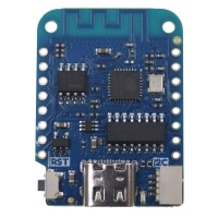
The brains of the system are a WEMOS LOLIN D1 Mini - a tiny ESP-8266 board about the size of a large postage stamp that runs Micropython and comes with a whole range of analog and digital I/O ports. It’s got a USB-C connector for power, and has wifi for connectivity. You couldn’t describe it as powerful, but it’s got plenty enough oomph to run an HTTP server and control the ultrasonic sensor.
The sensor is an HC-SR04 ultrasonic distance sensor that’s actually bigger than the D1 that controls it. It’s got two ultrasonic transducers and is supposedly accurate to +/- 3mm over 400cm. It connects directly to the digital I/O pins on the D1, and there’s a Micropython library which handles “debouncing” noisy results.

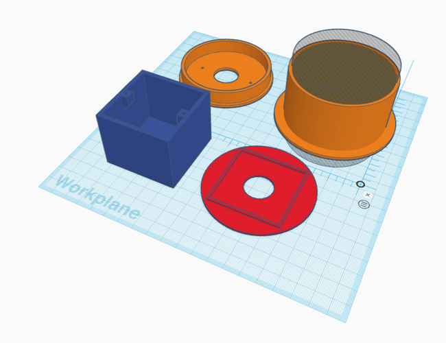
Both components are slotted inside a 3d-printed housing that I sized to drop inside the spare filling vent that each tank has. It’s not completely hermetically-sealed, but I figured that as you're allowed to store 4.500 litres of diesel under a house, it can’t be that volatile, and that IP7x-levels of seals aren't needed. A USB lead from an old phone charger plugs into a power socket in the tank room, and the D1 connect to the house wifi on the VLAN that I’ve set up for IoT devices.
How it works
I’ve set it up to take measurements while the heating system is running - the workflow runs like this:
- I’ve already connected a Shelly PM Mini Gen3 current metering device in series with the boiler which gives me data on the current that’s being pulled by the heating system. That’s fed into Home Assistant - the boiler eats about 7W on standby but jumps to over 300W as the fuel pump and air blowers kick in when it ignites. When the system is up to temperature the burners cut out, but the circulation pumps continues to draw about 50W
- The Shelly is monitored by Home Assistant. I’ve installed the Node-RED add-on to create the automation flows because I loathe YAML, and set up a workflow that runs every 5 minutes as a cron process
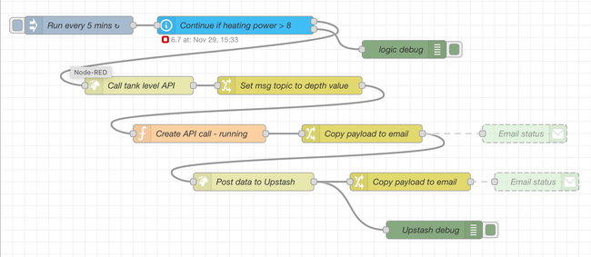
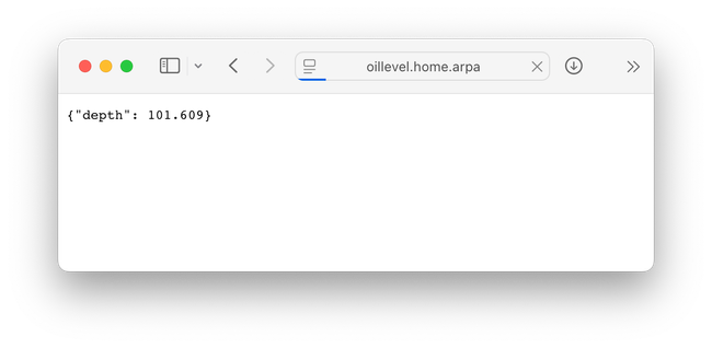
- If the boiler’s current draw is less than 10W I assume it's snoozing, and the workflow stops - but if it’s pulling more than 10W, then the heating is active. The workflow starts pinging the web server running on the D1, which fires a series of pulses to measure the distance between the sensor and the oil surface. The readings are averaged to smooth the data a bit, and handed back to Node-RED as a blob of JSON.
-
Node-RED uses that JSON to build a call to a Redis server that’s hosted as a managed service on Upstash. The HTTP call adds a new entry into the database with a timestamp key and the depth reading as the value. I was originally going to run an InfluxDB server on the Raspberry Pi that runs Home Assistant, but spinning up a free Upstash instance was way quicker.
-
there's also a graph on the Home Assistant "Heating" dashboard, but I haven't done too much there due to the above-mentioned YAML.
Over time, the sensor reading increases as the fuel level in the sensor-equipped tank drops, and given that I know the dimensions it’s possible to convert that into a litres-consumed figure. Multiply by 6 to account for the drop in the other tanks, and that’s a reasonably accurate result.
It’s obviously not as accurate as a flow meter which could monitor the diesel volume being pumped into the boiler, but it’s good enough. More importantly, it’s an early warning should the consumption suddenly jump, and it would be a way of knowing roughly when to reorder if I was going to be using the system long enough to need to.
Ideally, this whole system will be short-lived until the oil-based system gets pulled out and replaced by something less polluting - but in the meantime, it’s dragged an old-fashioned and analogue system into something approaching the modern world at a total cost of about 10€.